


USB Device Not Recognized? Troubleshooting USB Extenders and KVM Systems
A USB device may work normally when connected directly to a computer but stop working after a USB extender or KVM system is added.

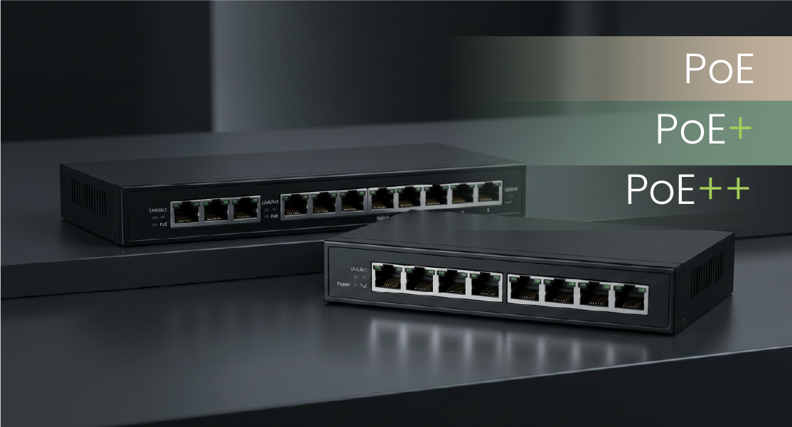
PoE, PoE+, and PoE++ all carry network data and DC power over an Ethernet cable. The main difference is the amount of power they can deliver.
Basic PoE works for many low-power devices, such as IP phones and some PoE IP cameras. PoE+ provides more power and is commonly used for PTZ cameras and wireless access points. PoE++ uses IEEE 802.3bt Type 3 or Type 4 to power network devices with higher power requirements.
There is no need to simply choose the highest PoE power available. Start with the powered device (PD): check which PoE standard it requires and how much power it needs. Then confirm the power sourcing equipment (PSE) per-port output, total PoE power budget, and transmission distance.
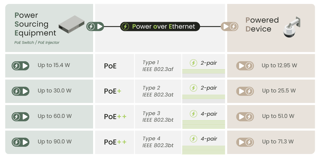
Maximum PSE output power is not the same as the maximum power available at the PD.
Cable resistance causes power loss, so the maximum power available at the PD is lower than the maximum power output by the PSE.
Also, do not assume:
PoE++ = 90 W
PoE++ generally refers to IEEE 802.3bt, which includes Type 3 and Type 4. Type 3 supports up to 60 W at the PSE, while Type 4 increases this to 90 W.
PoE stands for Power over Ethernet. It allows a remote device to receive network data and power through the same Ethernet cable. For example, a wireless access point can receive power through its network connection, reducing the need for a separate AC outlet and power cable at the powered device (PD).
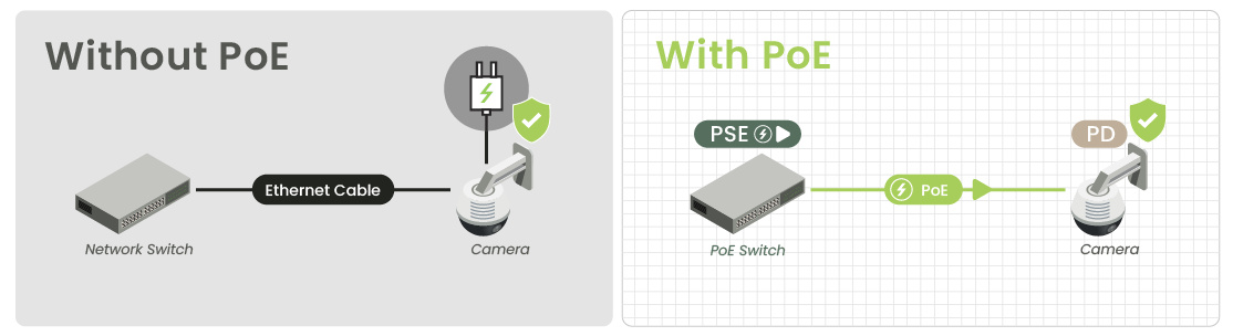
A basic PoE setup looks like this:
PoE Switch / Injector (PSE) → CAT Cable → PoE IP Camera (PD)
A PSE supplies PoE power. Common examples include:
A PD receives PoE power. Common examples include:
For equipment installed on ceilings, walls, outdoor poles, or other locations where adding a separate power source is difficult, PoE can reduce the need for additional power cabling.
IEEE PoE detects the connected device before supplying power. Passive PoE may supply power directly.
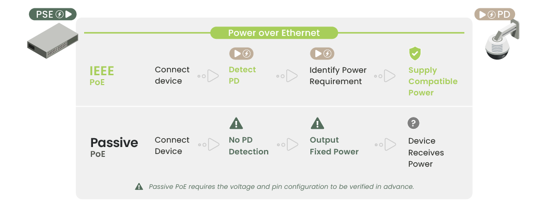
A PoE PSE compliant with IEEE 802.3af, 802.3at, or 802.3bt first detects the connected PD and then establishes power delivery according to the supported standard and power requirements.
Passive PoE does not use the same IEEE detection and classification mechanisms. It may output a fixed voltage on a specific pin configuration as soon as the connection is made. If the voltage, polarity, or pinout does not match the connected device, the equipment may fail to operate or could be damaged.
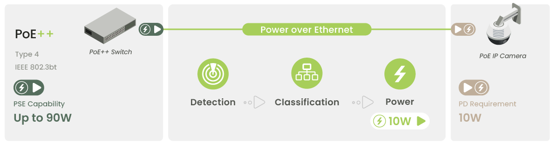
For IEEE-compliant PoE equipment, higher-power PSEs are designed to interoperate with lower-power IEEE PoE PDs.
For example:
PoE++ Switch → PoE IP Camera
This does not mean the switch sends the full 90 W directly to the camera. An IEEE PoE system uses detection and classification to identify the connected PD and determine its power requirements.

IEEE-compliant PoE devices are designed for interoperability, but Passive PoE and proprietary PoE implementations must be checked separately.

The most practical approach is to start with the PD and work backward through the system.

Start with the PD datasheet and check its IEEE PoE standard, PoE Type, and maximum power requirement.
Look for specifications such as:
For example, if a camera requires up to 22 W, an IEEE 802.3af PoE port cannot provide enough power at the device’s maximum load. Check whether IEEE 802.3at PoE+ is required instead.

Next, confirm how much power each port on the PoE switch, injector, or extender can provide.
If the device requires PoE+, a basic PoE port cannot be expected to provide the same power level.
Likewise, a switch labeled as PoE++ does not necessarily provide 90 W on every port.
Always check the actual product specifications.
First confirm the IEEE PoE standard and maximum power requirement of the PD, such as a PoE camera. Then choose a PSE—such as a PoE switch, injector, or extender—that provides the same or a higher PoE level.
Choose the PoE standard based on the PD’s requirements, not simply by selecting the highest-power PSE.
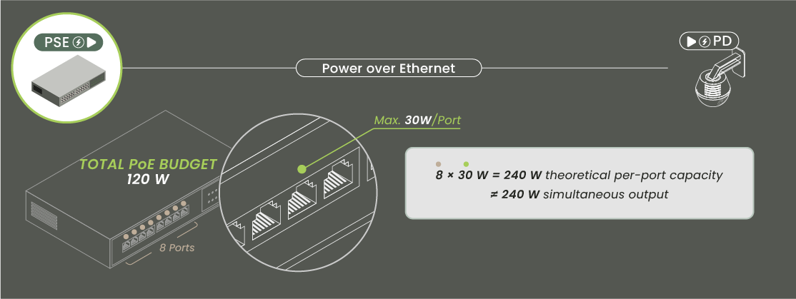
A multi-port PoE switch has another critical specification: its total PoE Power Budget.
Suppose an 8-port PoE+ switch specifies a maximum of:
30 W per port
A simple calculation gives:
8 × 30 W = 240 W
But if the switch has a total PoE Power Budget of only:
120 W
that does not mean all eight ports can simultaneously deliver 30 W.
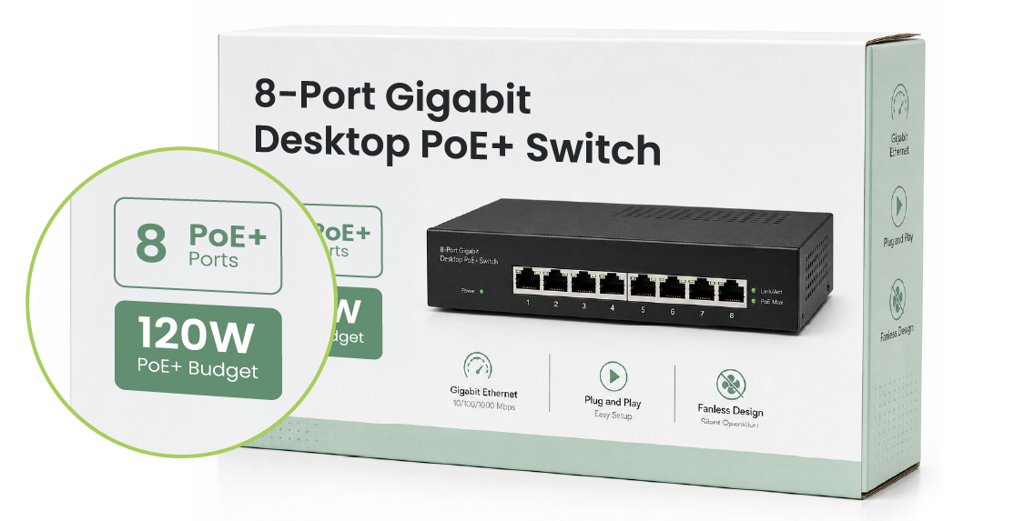
When planning multiple cameras or wireless access points, check both the per-port power rating and the total PoE Power Budget. Even if every port supports 30 W, the switch cannot power all ports at their maximum level at the same time if the total budget is insufficient.
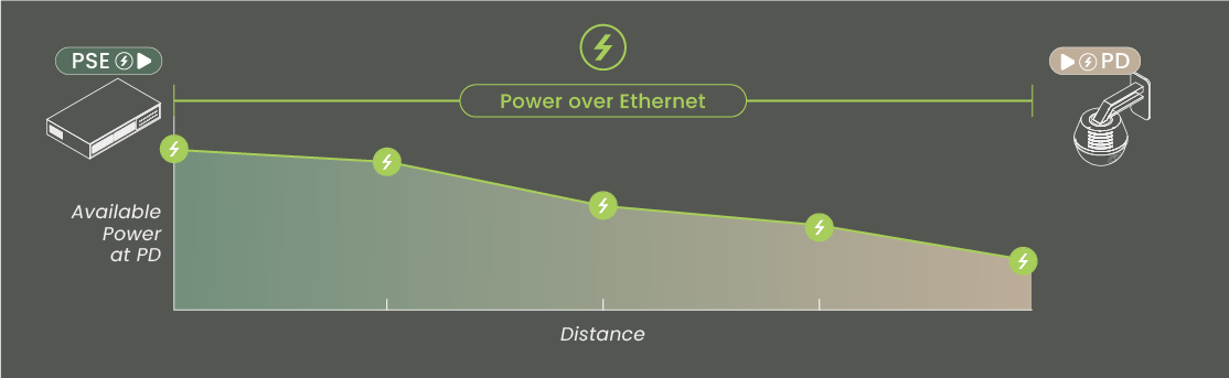
When PoE power travels over Ethernet cable, cable resistance causes voltage drop and power loss. Not all power leaving the PSE reaches the PD.
For example, an IEEE 802.3at PSE can output up to 30 W, while the maximum power available to the PD under the standard is 25.5 W. The difference between PSE and PD power accounts for the line loss permitted within a standard Ethernet channel.
The following example uses PoE+, PoE++ Type 3, and Type 4 to illustrate how increasing cable distance can affect the power available at the remote end.
Note: The table above is intended only to illustrate the trend of increasing power loss over longer distances. Values shown at 30 m, 50 m, and 80 m are simplified examples and are not fixed IEEE PD power values. Actual available power depends on PSE output voltage, PoE Type/Class, cable gauge and resistance, connectors, ambient temperature, and system configuration. For installation planning, refer to the Power Transmission Data provided by the PSE or extender manufacturer.
The standard Ethernet channel is designed for a maximum distance of about 100 m. This is the standard channel length for Ethernet data transmission; it does not mean power physically stops traveling beyond 100 m.
For installations beyond 100 m, confirm both whether the data link remains stable and whether enough power is still available at the remote PD.
Long-distance PoE requires checking both transmission distance and power available at the remote device.
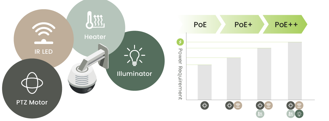
Not every IP camera uses PoE. For IP cameras that do, select the PSE based on the IEEE PoE standard and maximum power consumption specified for the exact camera model.
The following comparison assumes the camera supports IEEE PoE.
If one PoE switch powers multiple cameras, also check the total PoE Power Budget.
Features such as PTZ motors, IR LEDs, heaters, and illuminators can increase camera power consumption, especially during startup or when several functions operate at the same time.
Do not choose the PoE standard based only on the camera type. Check the maximum power requirement of the actual model.
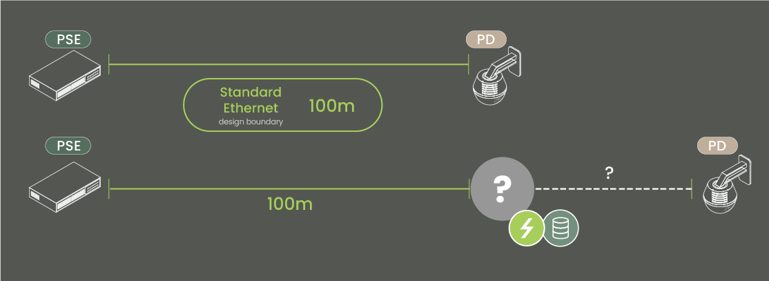
The standard Ethernet channel is designed for a distance of about 100 m. If a PoE camera or other PD must be installed beyond this distance, check both the extended data link and the PoE power available at the remote end.
Rewiring is not always necessary. Start by checking what cable infrastructure is already available, then choose the appropriate extension method:
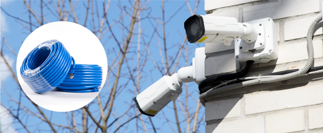
If CAT5e, CAT6, or higher-grade network cabling is already installed, a long-distance Ethernet / PoE extender can extend both network data and PoE without replacing the entire cable run simply because it exceeds 100 m.
Long-distance PoE should not be selected based only on the maximum transmission distance. Cable resistance increases voltage drop and power loss over longer runs, so also check:
IP Camera over Coax – Campus Surveillance Upgrade Case Study
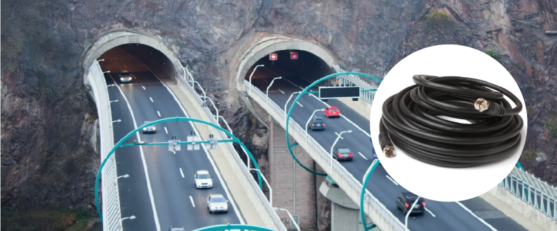
Many existing analog CCTV systems already use RG59, RG6, or similar coaxial cabling. When upgrading to PoE cameras, the existing coax does not necessarily need to be removed and replaced if it is still in good condition.
Ethernet over Coax / PoE over Coax can carry Ethernet over the existing coaxial cable. Models with PoE can also deliver both data and power to the remote device, making them useful for roads, tunnels, campuses, and other CCTV upgrades where recabling would be costly. SC&T’s current Ethernet over Coax solutions are also designed around reusing existing coaxial infrastructure for IP/PoE camera upgrades.
Check:
As with long-distance PoE over Ethernet, longer distances require checking the actual power available at the remote end—not just the product’s maximum transmission distance.
Road Surveillance System Upgrade
IP/PoE Surge Protector Solution
PoE, PoE+, and PoE++ all carry data and power over Ethernet cabling. The main difference is the standardized amount of power each can provide.
Use the following sequence when selecting a PoE system:
If the distance exceeds the standard Ethernet channel, do not compare extenders based only on how far they can transmit.
For a PoE system, the more important questions are:
Can the data link remain stable, and will enough power still be available when it reaches the remote device?
For remote CCTV installations and sites with existing CAT or coaxial cabling, SC&T provides long-distance PoE and Ethernet over Coax solutions that can be selected according to the existing cable infrastructure, transmission distance, and remote power requirements.
Copyright © SC&T. All rights reserved. No part of this website may be reproduced or distributed without prior written permission.
A USB device may work normally when connected directly to a computer but stop working after a USB extender or KVM system is added.
AV requirements in a medical simulation center go beyond recording a training session. In addition to room camera feeds and audio, a session may require recording patient vital signs, ultrasound images, or displays from other equipment. Some content may need to be sent to a control room or observation area for live viewing and later used during debriefing.
USB-C Power Delivery (USB-PD) has quickly become a must-have feature in meeting room presentation systems. It allows users to charge their laptops, output video, transfer data, and even connect to cameras, touchscreens, or other USB peripherals—all with just one USB-C cable. Removing external power supplies and adapters reduces failure points, ensuring an intuitive workflow and bulletproof system reliability.

1. All specifications are subject to change without notice.
2. Brand and product names mentioned are trademarks of their respective companies.
3. The terms HDMI, HDMI High-Definition Multimedia Interface, HDMI Trade dress and the HDMI Logos are trademarks or registered trademarks of HDMI Licensing Administrator, Inc.


